Description
Build your own instant camera with removable, reusable e-paper photos.
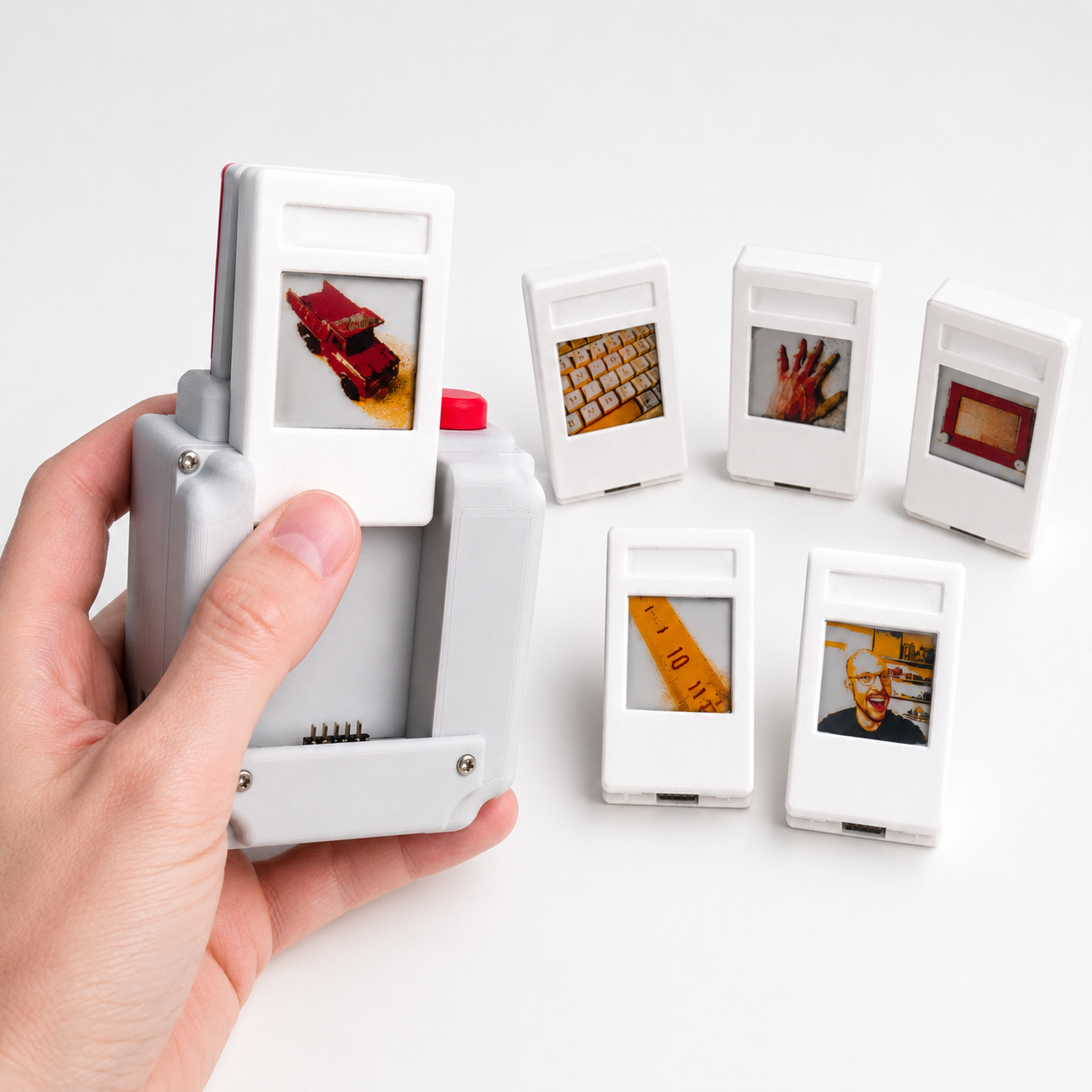
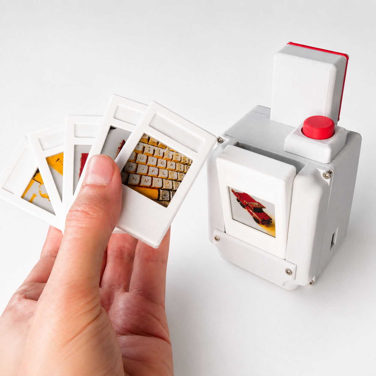
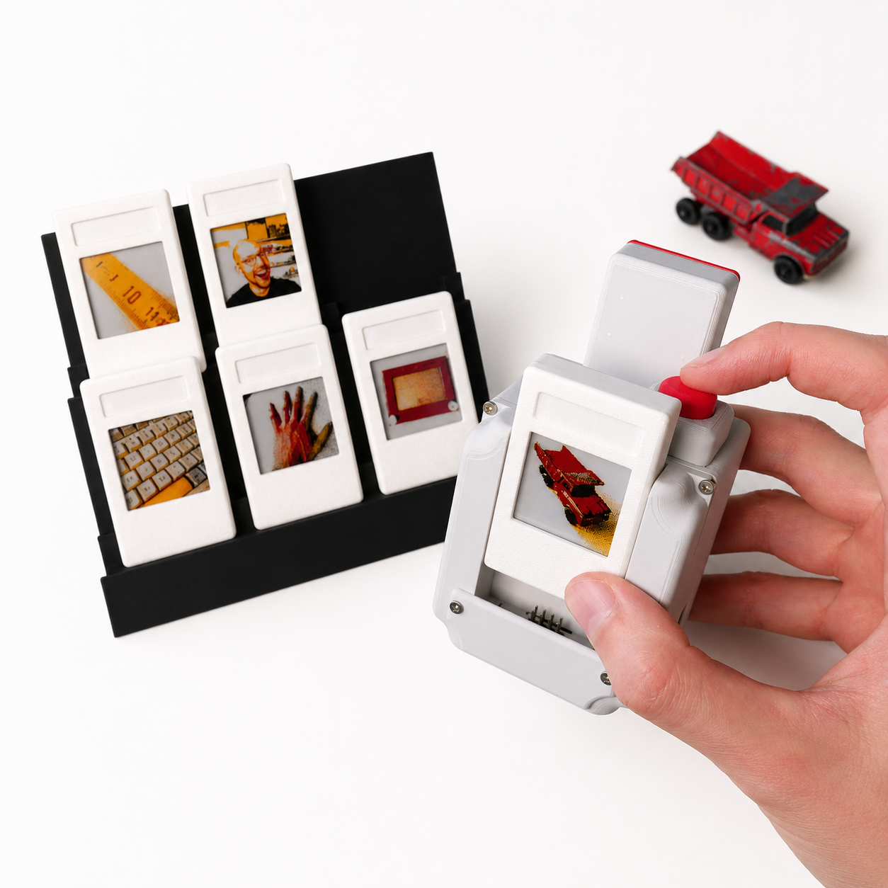
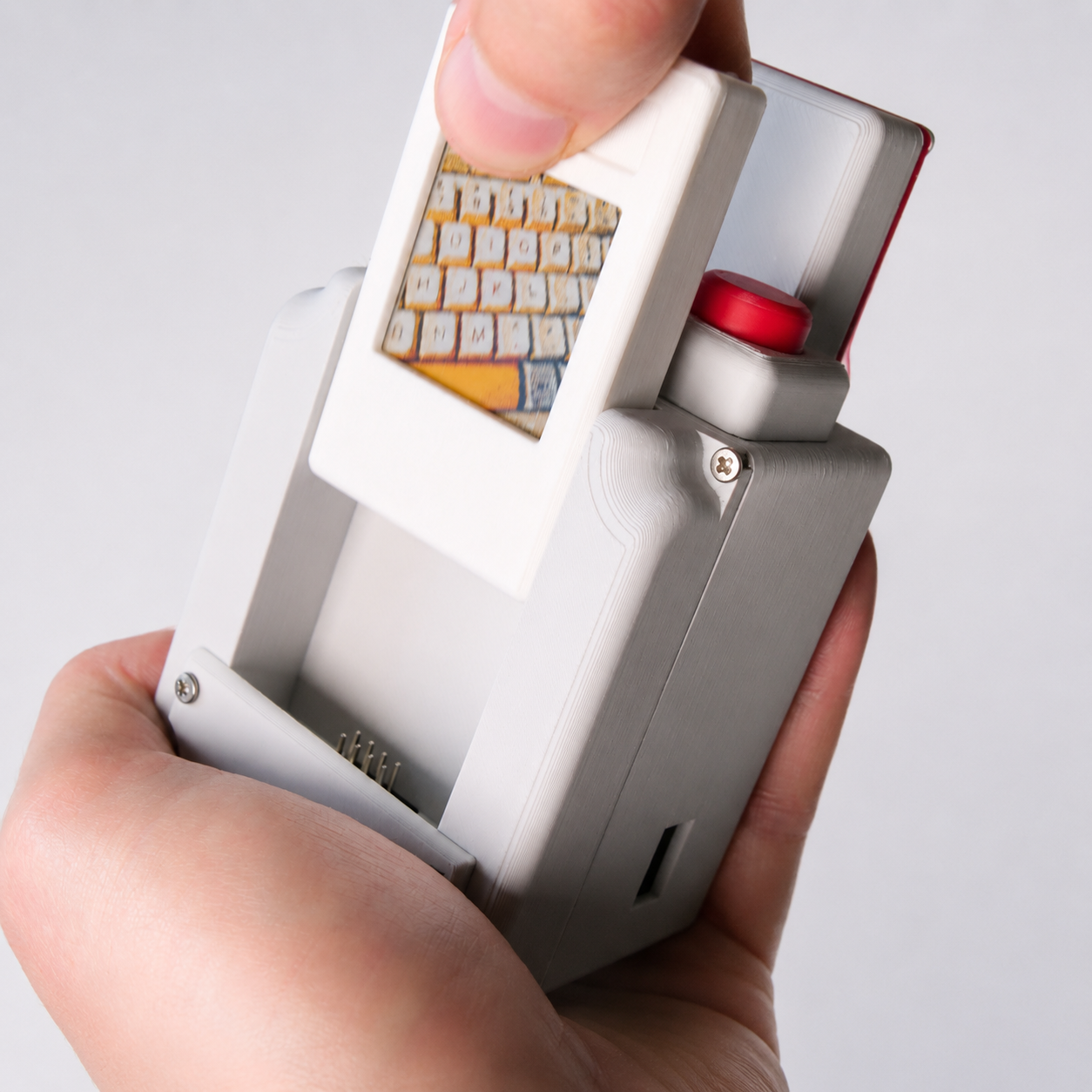
This camera uses small four-color e-paper displays as physical “digital film”. Take a photo, wait for it to appear on the cartridge, pull the cartridge out and insert a new one. Because e-paper retains its image without power, every cartridge becomes a tiny physical photograph that you can keep, display and rewrite later.
I designed the camera around a Raspberry Pi 3 A+, a 5 MP camera module and inexpensive 1.54-inch e-paper displays. The complete build costs approximately €127 with six photo cartridges.
The project files include everything I used to build mine: the FreeCAD source file, STL files, electrical wiring diagram, complete parts list, Raspberry Pi software, modified e-paper driver, and an image-processing test suite for experimenting with dithering, contrast, sharpness and other processing settings.

Difficulty
I would call this an intermediate DIY project.
The mechanical assembly and soldering are fairly straightforward, but this is probably not a good first electronics project. You should be reasonably comfortable with soldering, using a Raspberry Pi over SSH, installing Linux packages, enabling interfaces such as SPI, and doing some basic troubleshooting if something behaves differently on your hardware.
You do not need to design PCBs or write the software yourself.
Parts and approximate cost
| Part | Qty | Approx. cost |
|---|---|---|
| 3D-printing filament | — | €4.00 |
| Raspberry Pi 3 A+ | 1 | €32.00 |
| 8 GB microSD card | 1 | €8.00 |
| WeAct 1.54″ black/white/red/yellow e-paper module | 6 | €53.34 |
| Waveshare Li-polymer Battery HAT | 1 | ~$18.99 |
| 12 × 12 mm push button | 1 | €1.00 |
| 5 MP OV5647 autofocus camera + 15 cm ribbon | 1 | €5.59 |
| 2×4 right-angle female 2.54 mm headers | 6 | €2.00 |
| 2×4 right-angle male 2.54 mm header | 1 | €1.00 |
| M2 screws | — | ~€2.00 |
| Total with six cartridges | ~€127 |
The display modules I used are the WeAct Black/White/Red/Yellow 1.54-inch SPI e-paper modules. The exact headers matter mechanically, so check the dimension drawings included in the project files before ordering.
I used a Raspberry Pi 3 A+ because its smaller form factor fits the enclosure. A regular full-size Raspberry Pi will not fit the provided shell without redesigning it.
The camera module I used has the standard 15-pin ribbon connector suitable for the Pi 3/4-style camera connector. Some Pi models, including the Zero family and newer Pi models, use a different ribbon connector, so check compatibility before ordering.
3D printing
My version uses:
gray for the camera body, red for the shutter button/accent, white for the photo cartridges, and black for the six-photo display stand.
The cartridges contain a fairly challenging bridge around the thumb-grip area. On my Bambu X1C, the default bridge settings produced a very ugly underside.
What eventually worked well for me was:
Bridge flow ratio: 1.8
Bridge speed:      10 mm/s
Your printer and filament may behave differently, so treat these as a starting point rather than universal settings.
The cartridge uses a printed hinge and snap-fit construction, so it does not require screws.
Screws
My build uses approximately:
Shutter button frame        4× M2×6 mm
8-pin header lock plate     2× M2×8 mm
Main cover                  4× M2×8 mm
Front cover                 2× M2×6 mm
Camera module               4× M2×8 mm
Camera cover                4× M2×6 mm
You will therefore need roughly:
10× M2×8 mm
10× M2×6 mm
One small caveat: M2×8 is slightly too long for my camera module while M2×6 is slightly too short, so take some care there.
Raspberry Pi setup
I used Raspberry Pi Imager to install the latest compatible Raspberry Pi OS without the desktop environment onto an 8 GB microSD card.
During imaging I configured Wi-Fi and used:
hostname: polaroid
username: polaroid
That means I can normally reach the camera over the local network using:
ssh polaroid@polaroid.localCopy the contents of the included epaper-polaroid folder onto the Raspberry Pi.
Install the required Python packages:
sudo apt update
sudo apt install -y python3-pil python3-numpy python3-gpiozero
Then enable SPI:
sudo raspi-configChoose:
Interface Options / Peripherals
→ SPI
→ Enable
The camera can then be started manually from the project directory with:
python3 main.pyStarting the camera automatically
I configured mine as a systemd service so the camera software starts automatically when the Raspberry Pi boots.
Create:
sudo nano /etc/systemd/system/epaper-camera.serviceand add:
[Unit]
Description=E-paper Polaroid Camera
After=multi-user.target

[Service]
Type=simple
User=polaroid
WorkingDirectory=/home/polaroid/epaper-polaroid
ExecStart=/usr/bin/python3 /home/polaroid/epaper-polaroid/main.py
Restart=on-failure
RestartSec=2
Environment=PYTHONUNBUFFERED=1

[Install]
WantedBy=multi-user.target
Adjust the username and paths if you configured your Pi differently.
Then run:
sudo systemctl daemon-reload
sudo systemctl enable epaper-camera.service
sudo systemctl start epaper-camera.service
Check its status with:
sudo systemctl status epaper-camera.serviceWatch the camera’s console output live with:
journalctl -u epaper-camera.service -fAnd if you want to stop the service temporarily so you can run the program manually:
sudo systemctl stop epaper-camera.serviceImage processing
The e-paper display can only produce black, white, red and yellow, so normal photographs need quite a bit of processing before they look good.
The included:
image_processing_test/test_image_processing.pyis intended for experimenting with the image-processing pipeline before putting settings on the camera.
I used it to tune things such as contrast, brightness, saturation, sharpness and dithering. Feel free to modify it, add completely different filters or generally make the camera much weirder than mine.
The final Raspberry Pi software contains the settings I used in the video and supports both dithered and non-dithered modes.
E-paper driver
The included e-paper driver is not simply the original manufacturer driver.
I modified the driver so this particular display works correctly with the Raspberry Pi setup used in this project, including timeout handling so the program does not sit indefinitely waiting for a cartridge that failed to initialize.
Use the driver supplied with the project rather than replacing it with a seemingly equivalent off-the-shelf version.
Wiring
Be careful with the GPIO-header orientation. Looking at Raspberry Pi pinout drawings from the opposite orientation is an extremely easy way to mirror the entire connector.
The drawing included with the project files should be considered the primary wiring reference.
On my modules, the wire colors were:
| Function | Raspberry Pi |
|---|---|
| Push button | GPIO21 + GND |
| CS | GPIO8 |
| SCLK | GPIO11 |
| DC | GPIO25 |
| MOSI | GPIO10 |
| BUSY | GPIO24 |
| RST | GPIO17 |
| Ground | GND |
| Power | 3.3 V |
Do not assume your wire colors are identical to mine. Verify the pin functions on your own module before connecting it.
Also note that the e-paper module is powered from 3.3 V, not 5 V.
Important notes about the cartridges
This project uses the e-paper modules in a somewhat unusual way: they are repeatedly physically connected and disconnected from the running camera.
I do not know the rated number of mating cycles for this particular combination of header and display module, nor have I characterized what happens electrically if the cartridge is removed halfway through an e-paper update.
For that reason, I recommend:
Do not remove a cartridge while an image is being written. Wait until the camera indicates that the operation has completed before swapping it.
The display documentation also warns against leaving the e-paper module continuously powered unnecessarily. The supplied software puts the display into sleep mode after writing an image.
During my build I also found that the GND through-hole pad on every one of my WeAct modules was unusually difficult to solder. It appears to sink a lot of heat. If solder refuses to wet that pad while all the others work normally, use sufficient flux and a larger amount of heat rather than assuming the connection is good. A bad GND joint caused intermittent cartridge failures on my prototype.
What’s included
The download contains the FreeCAD project so you can modify the complete mechanical design, ready-to-print STL files for the camera, cartridges and display stand, the electrical wiring diagram and header dimensions, a complete parts list, the Raspberry Pi camera software and modified e-paper driver, and the separate image-processing test software.
This is the same design and software used for the camera shown in my video.
License / Usage
These files are provided for personal, non-commercial use only. You may build the camera for yourself and modify the files for your own use.
You may not sell, redistribute, upload, or commercially use the design files, software, modified versions of the files, or physical builds based on this project without my prior written permission.
If you’d like to use the project commercially, please contact me first.